VISIE 3D scanners are Investigational Devices and are not available for sale.

VISIE 3D scanners are Investigational Devices and are not available for sale.
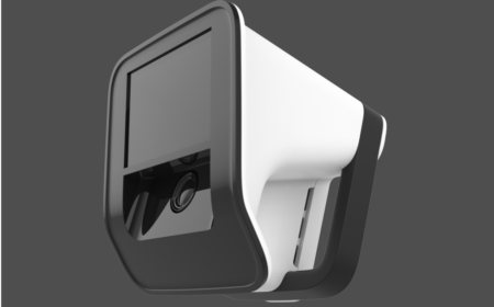
Computer-assisted surgery and related workflows depend on geometrically accuratethree-dimensional information for registration, guidance, and measurement. VISIE’snovel structured-light scanner (see Fig. 1) captures that information directly fromexposed anatomy. It addresses the problems of conventional navigated orthopedicworkflows that involve point-by-point acquisition, often requiring rigid fixation of areference array and repeated contact probing through cartilage to build a sparsesurface model.
This scanner is part of our spatial computing system that currently tracks anatomy(scans and registers) 20 times per second without it requiring reference array fixation.In this White Paper we describe accuracy measurements of the scanner relevant toregistration for computer-assisted surgical navigation, robotics, and AI workflows thatdepend on accurate anatomic capture.
This White Paper shows that VISIE delivers the positional fidelity required for surgical use. In sphere-based metrological bench-testing, the largest scanning errors remained below 2 mm. In cadaveric testing, control experiments that used implanted spherical fiducials arranged around the femur resulted in all measured sphere localization errors being less than 0.6 mm, relative to clinical CT scans. Taken together, these results show that VISIE scans measure feature size and spatial distribution with the geometric fidelity required for computer-assisted surgery, and data capture for AI training.
What distinguishes this scanner is its particularly high signal-to-noise ratio and its abilityto capture more complete anatomy during 3D acquisition at relatively close workingdistances, approximately 40 cm, appropriate for surgery. Its unique method of castingpatterned shadows through the scanning volume, rather than projecting a lens-formedpattern, gives the projected pattern a high depth of field even at close distances.
A linear LED array is used for projecting light on the object from multiple angles,improving illumination across the exposed surface. The scanner avoids conflict withmodern surgical luminaires by using near-infrared structured light. Each scan is capturedin a fraction of a second. Together, these features support superior digitization ofanatomy and provide stable, repeatable geometric features for registration in typicalsurgical exposures for total knee arthroplasty [1].
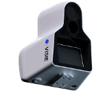
Figure 1. A render of the VISIE structured-light scanner used in the bench and cadaveraccuracy studies
To evaluate scanner accuracy, we employed two methods. First, we used methods described in ISO 10360-13 [2]. That standard uses a sphere-based metrology framework that naturally evolved from traditional methods for evaluating the accuracy of physical CMMs
(coordinate measurement machines). The gold standard for our assessment was a NIST-traceable ball-bar artifact with two 1-inch spheres separated by 200 mm. It was placed throughout a 200 x 200 x 300 mm working volume in a variety of prescribed positions
(see Fig. 2), and the resulting data were analyzed for sphere size and center-to-center spacing error.
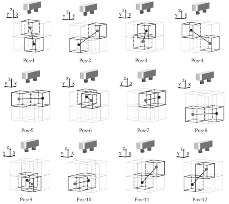
Figure 2. ISO-style arrangement of the twelve ball-bar positions used to distribute the two-sphere artifact through the VISIE sensor measurement volume for single-view and multi-view evaluation [2].
As a second test, VISIE also assessed accuracy in a cadaveric study simulating practical clinical use, this time using implanted fiducial spheres digitized both by the optical scanner and by a clinical CT scanner, which was the gold standard in this case. This latter approach leverages techniques developed for the evaluation of positional accuracy of neurosurgical navigation systems [3]. Additional procedural detail is provided in the Appendix: Detailed Methods.
Figure 2 shows the ISO-prescribed distribution of the calibrated two-sphere artifact through the sensor measurement volume. Figure 3 shows our scanner mounted on a robot for automated positioning of the VISIE scanner relative to the ball-bar, as prescribed in Figure 2. Table 1 reports the error measurements of our scans from those acquisitions. In this bench study, the worst single-view (single-scan) error in the measure of the separation between the centers of the spheres (“distortion error”) was 1.17 mm and the largest single-view error in the measured sphere diameter (“probing size error”) was 1.38 mm.
These errors occurred with the spheres placed at positions furthest from our scanner, and are still well within the 2 mm error associated with state-of-the-art navigation devices cleared by the FDA for surgical navigation. Although not in Table 1, it should be noted that the mean absolute error for these measurements was 0.48 mm (sphere separation) and 0.313 mm (sphere size). The largest multi-view sphere-separation error was 0.38 mm and the largest multi-view sphere-size error was 0.18 mm.
These “multi-view” errors are determined by measuring a single assembled point cloud comprised of co-registered scans taken at all 12 positions shown in Fig. 2
(one scan per position). This was done two more times (with slightly different ball-bar positioning) to create two more “multi-view” measurements. The largest multi-view errors are materially lower than the largest single-view errors, indicating that the merged reconstruction preserved sphere-centroid geometry across the working volume and benefited from an averaging effect. For orthopedic navigation devices, the relevant performance expectation is commonly framed around errors of less than 2 mm; these measured values are well within that level of accuracy.
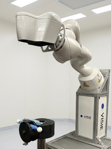
Figure 3. Accuracy assessment setup with robot arm holding the scanner for automated positioning relative to the NIST-traceable fiducial ball-bar, with spheres visible. The scanner was placed such that the ball-bar occupied positions in the scanning volume according to Figure 2.
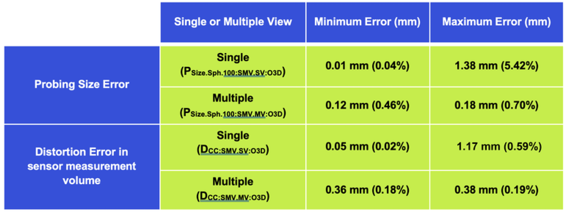
Table 1: Probing Size Error (sphere size error) and Distortion Error (sphere separation error) measured in VISIE scans of NIST-traceable sphere ball-bars. Minimum and maximum error measurements given. Description of “Single” and “Multiple” values and methods are described in Method Overview and Appendix: Detailed Methods. The P and D symbols in parentheses correspond to ISO 10360-13:2021 [2].
The second test of scanner accuracy was designed to measure scanner accuracy in a more representative clinical environment, as shown in Fig. 4. Here, we use spherical fiducials to provide a control baseline registration for comparison with our registrations of the femur that are performed purely using anatomic features, and will be the topic of [1].
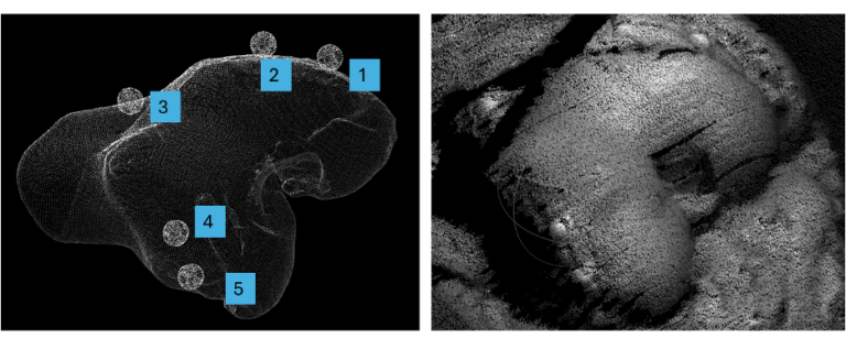
Figure 4. Sphere fiducials arranged around the femur in the cadaver control experiment, alongside an optical scan view of the knee. The same centroid-based geometry used in the ISO-style ball-bar study is used here to establish and evaluate CT-to-optical registration [1,3].
A typical fiducial configuration is shown in Fig. 4. In this study the sphere centroids are determined from our optical scan (scan shown on the right in Fig. 4) and those centroids registered to the sphere centroids determined from the corresponding CT scan (Fig. 4, left, shown with femur and spheres segmented). The mismatch in spatial alignment between the two sets of sphere centroids (fiducial residual error) for the scans in Fig. 4 was 0.1 mm RMSE.
This excellent alignment was obtained from fiducials distributed across the femoral scan volume, supporting the clinical applicability of the method. Other datasets showed similar error levels, with ~0.3 mm RMSE typical [1].
As discussed below, the bench and cadaver studies show that the scanner captures anatomy faithfully and localizes it with accuracy appropriate for surgical use.
The reported results are meaningful in two established contexts. First, the bench study places the scanner within the traditional sphere-based framework used for optical 3D accuracy assessment, where known sphere geometry and sphere-center spacing provide a direct measure of geometric fidelity [2]. Second, the cadaver control workflow shows that the same centroid-finding capability carries into a surgical registration setting, where CT-derived and optically derived fiducials can be aligned with sub-millimeter residual error in the illustrated example and similarly small errors in other cadavers [1,3]. This supports the view that the scanner recovers shape and position within the tested working volume with accuracy suited to anatomic-based navigation. These results are also relevant beyond immediate image-guided registration. A scanner that can recover anatomy and fiducial geometry with this level of consistency can support data generation for AI-based navigation and robotic workflows, where training quality depends on reliable geometric input and repeatable spatial correspondence between anatomy, images, and physical space. In that sense, the scanner is not only a registration device; it is also a potential source of high-quality geometric data for future navigation, robotics, and image-guided-surgery systems.
Across both the sphere-based bench study and the cadaver fiducial study, the VISIE structured-light scanner showed errors within the sub-2-mm range expectation commonly applied to orthopedic navigation devices. The bench results stayed below that threshold even at their worst observed values, and the cadaver registration errors were smaller still. These findings support the conclusion that VISIE measures feature size and spatial distribution with the fidelity required for image-guided surgery, navigation, robotics, and related AI-enabled surgical workflows.
[1] Rapid, Touchless Registration of the Distal Femur to Preoperative CT Scans for Total Knee Arthroplasty Using Intraoperative Structured Light 3D Imaging. In Preparation.
[2] ISO 10360-13:2021. Geometrical product specifications (GPS) – Acceptance and reverification tests for coordinate measuring systems (CMS) – Part 13: Optical 3D CMS. International Organization for Standardization. https://www.iso.org/standard/74957.html
[3] Maurer CR Jr., Fitzpatrick JM, Wang MY, Galloway RL Jr., Maciunas RJ, Allen GS. Registration of Head Volume Images Using Implantable Fiducial Markers. IEEE Transactions on Medical Imaging. 1997;16(4):447-462.
Please download the whitepaper for full appendix with detailed methods.